  __  __
 |  \/  |___  __ _ _ _  ___ _ _  _ __  ___
 | |\/| / _ \/ _` | ' \/ _ \ ' \| '  \/ -_)
 |_|  |_\___/\__,_|_||_\___/_||_|_|_|_\___|
________________________________________________________________________
How I started making a Monome and ended up with something else.
The following images and text is only interesting to those who would like
to know how I build my Monome40h Arduino clone and ended up with something
different. The text contains lots of nerdish references and dry jokes, the
images are solder/electro-pron (at best). For those of you that don’t want
to read a lot of text, just scroll down and there will be a video with the
highlights from this text)
Basics:
The Monome 40h is a 8×8 button and led grid that is used as an interface to
your musical programs/synths etc. The Arduino is a microprocessor based
hardware interface with development environment on the computer.
The Arduinome is a merge of the both, creating a clone of the original Monome
with the use of an Arduino as brain. It was one of these I tried to build,
but failed with as you will read further down, so instead I created something
that suited my skills better and something I probably will use a lot more 🙂
Thus I dubbed my contraption to Moanome.
Features of my Arduinome:
* 8×8 bright LED’s
* 8×8 arcade buttons (I mounted the LED’s inside)
* Handcrafted box.
* Midi-out.
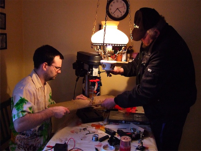
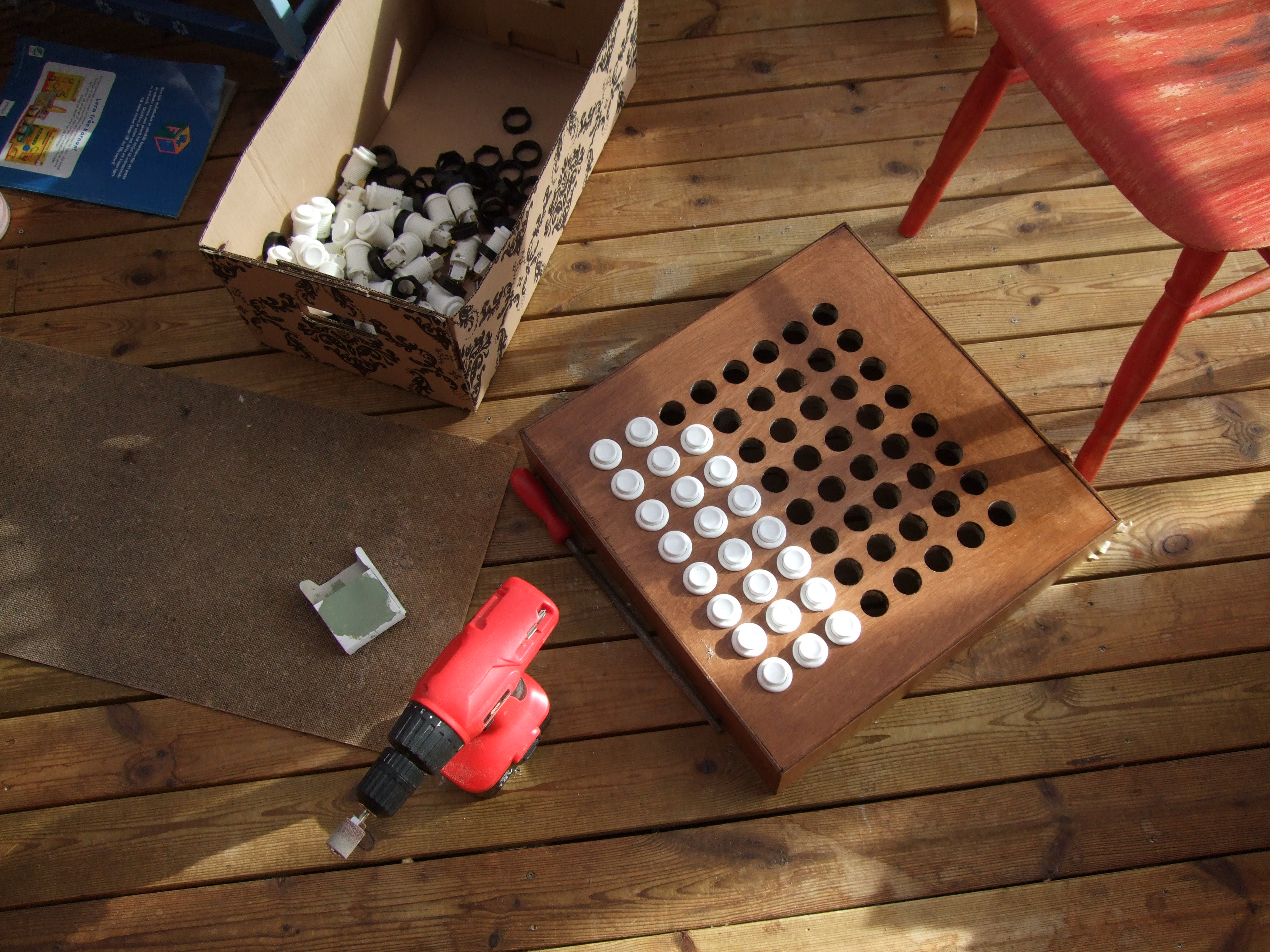
Building the Box:
I had some prior experience in mounting such arcade buttons on wood, but that
did not prepare me for how long it would take me building a box from start
to end. I used 3mm plywood as outside and a piece of an old IKEA wardrobe
that I had in the garage. So I spent many hot summer afternoons in the garage
sawing and drilling. I didn’t bring the camera out so there are few images
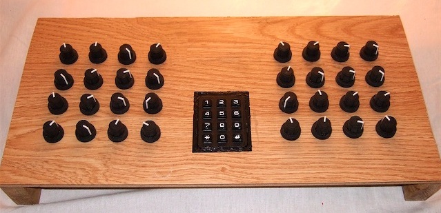
from this part of the build-process. These are two from the finished (almost).
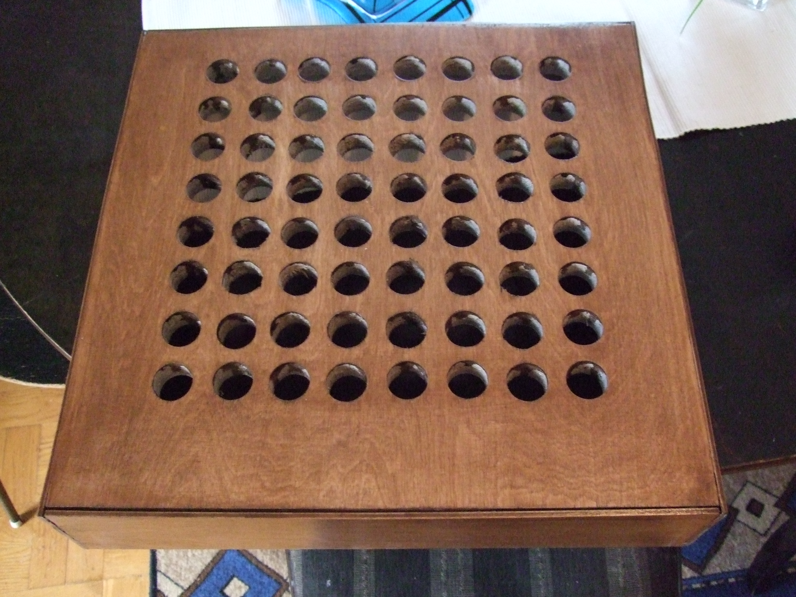
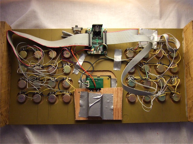
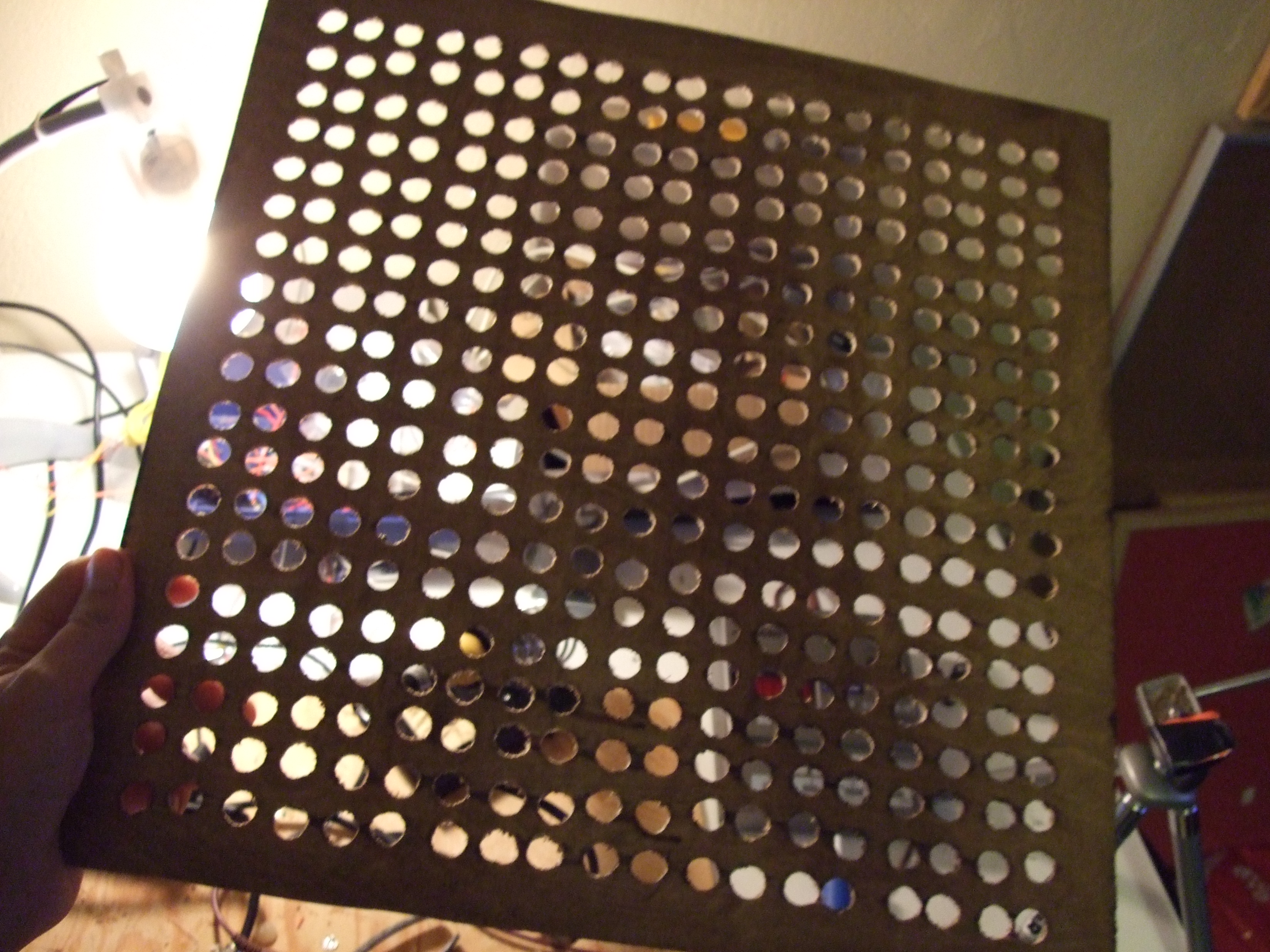
I didn’t do a backplate here though, I made one later, or, I made two, first
I tried to make one out of plastic but that was to squiggly, so I made one from
wood instead. I drilled loads of holes so you can sort of se the inner workings
of my Moanonme.
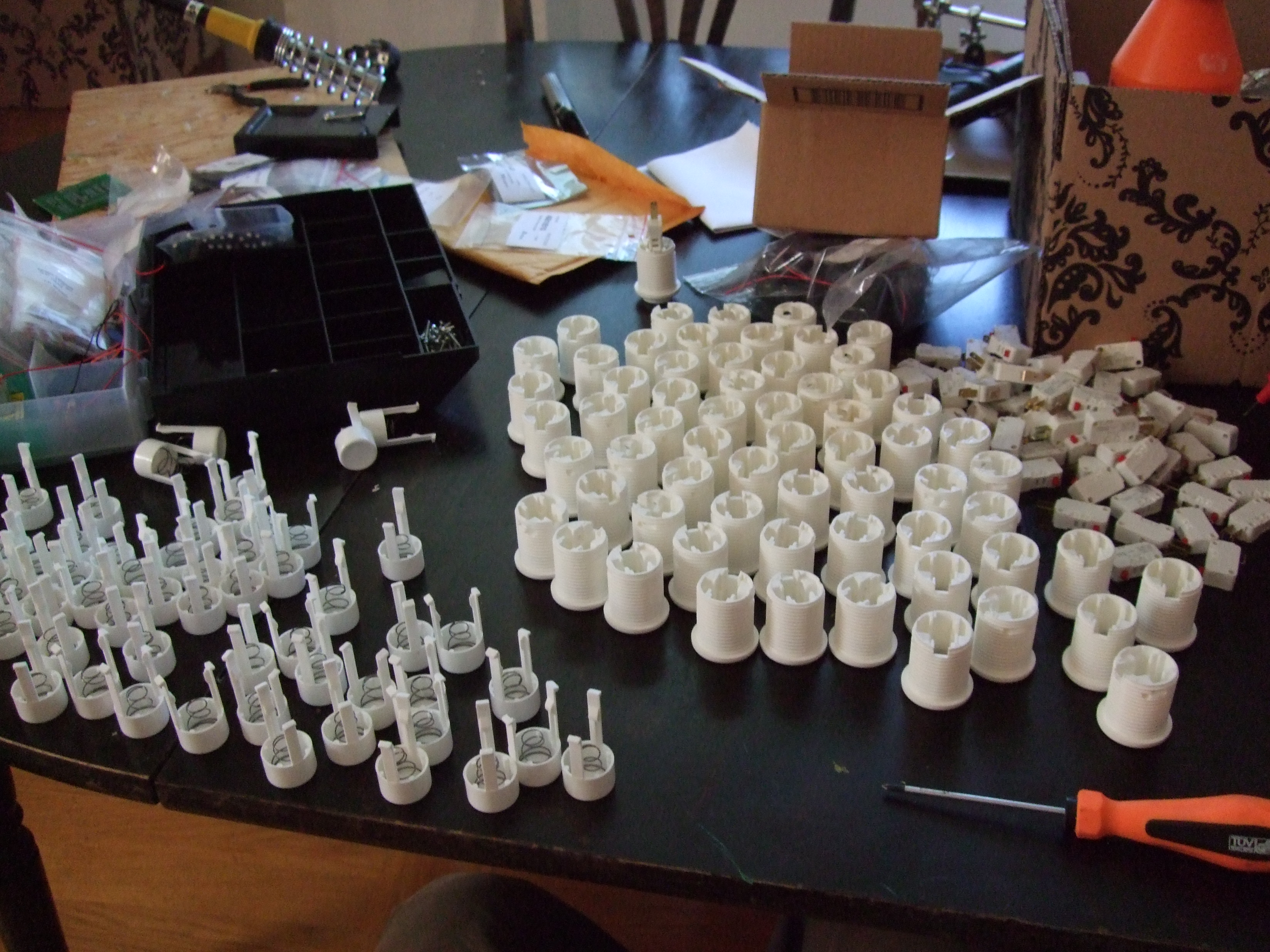
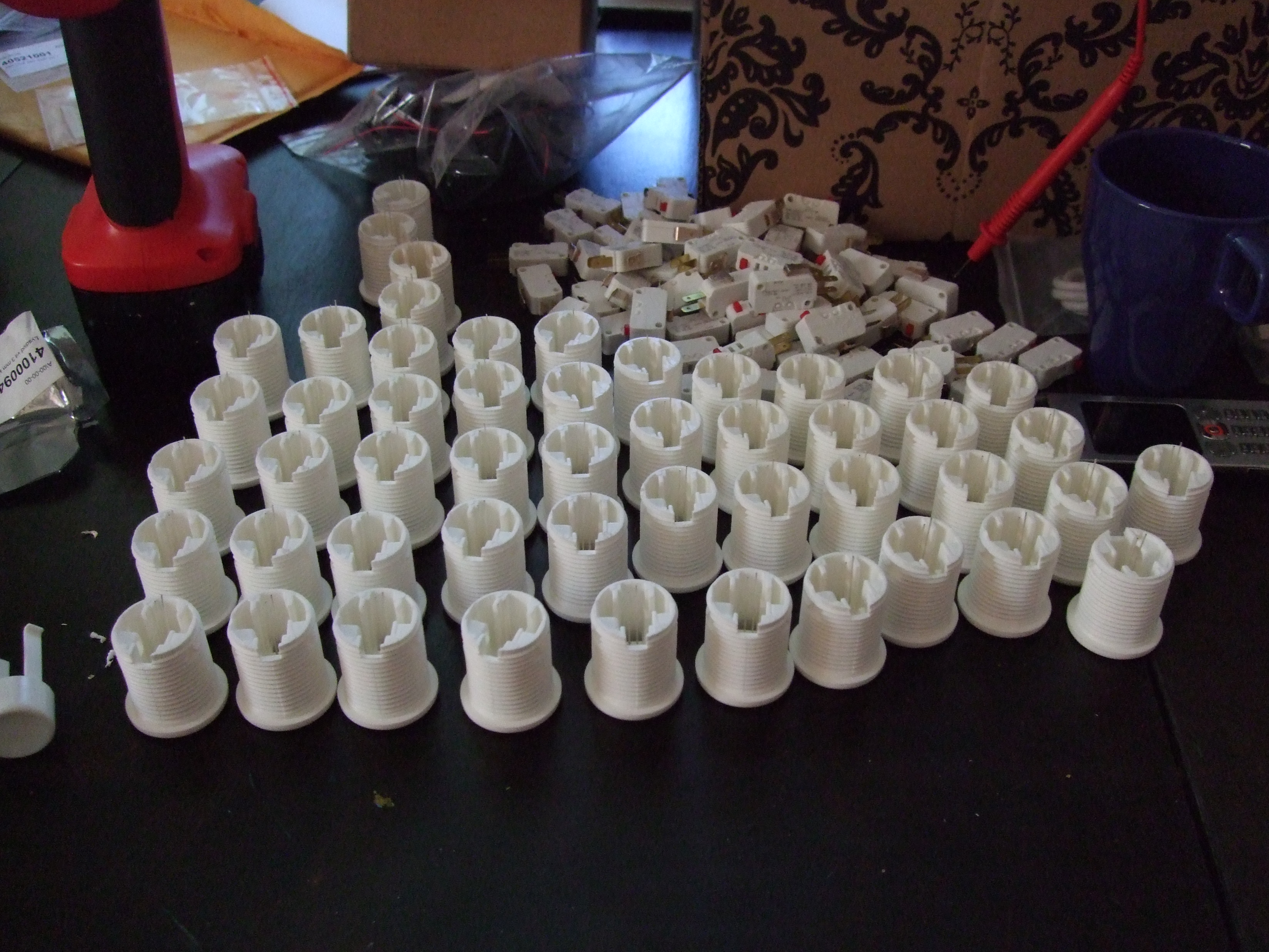
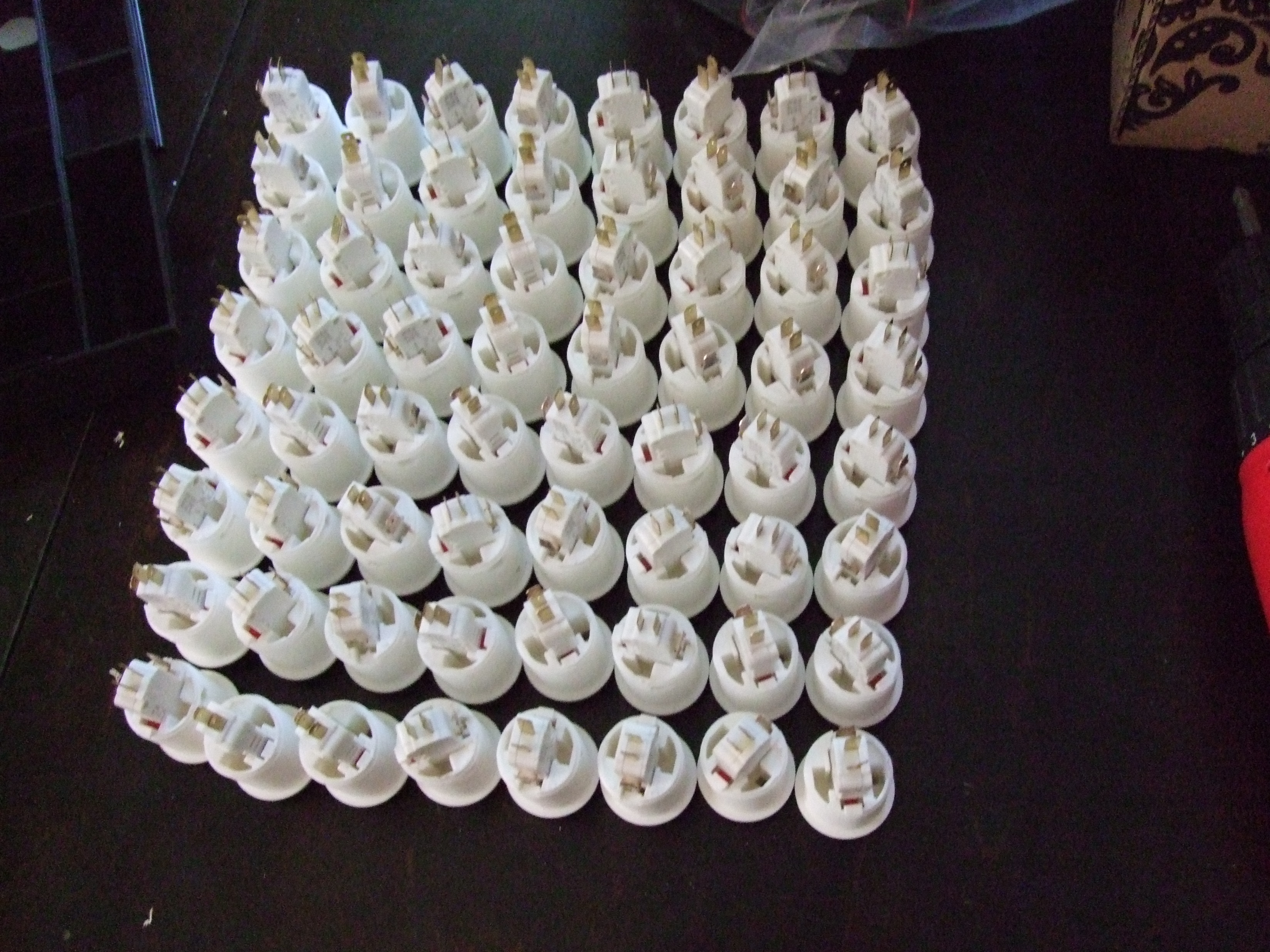
Modifying the arcade buttons:
I found an instructable on how to add a LED to your arcade-button, it’s really
simple. Dismantle the arcade button, drill a hole for the LED, insert the LED,
Put everything together. Sounds easy enough right? well try boring, that what
it was doing that 64 times. Funny story about the buttons, if you want to buy
a bunch like I did, you better have a friend in the USA because the UK reseller
really adds a hefty amount to the price. Thanks again Nils and snygge-Mange
for getting me these.
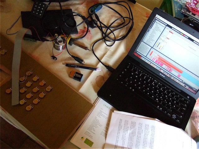
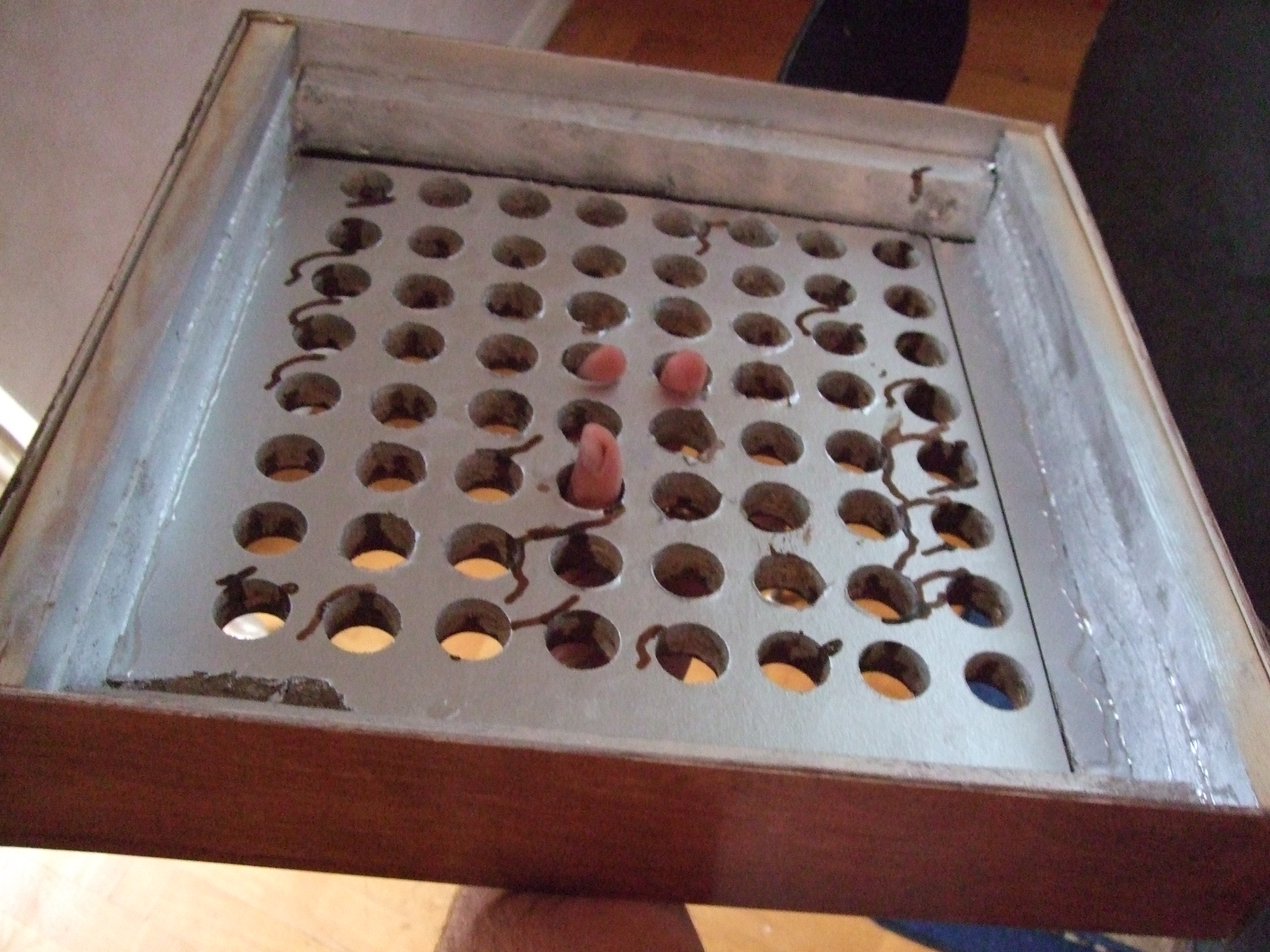
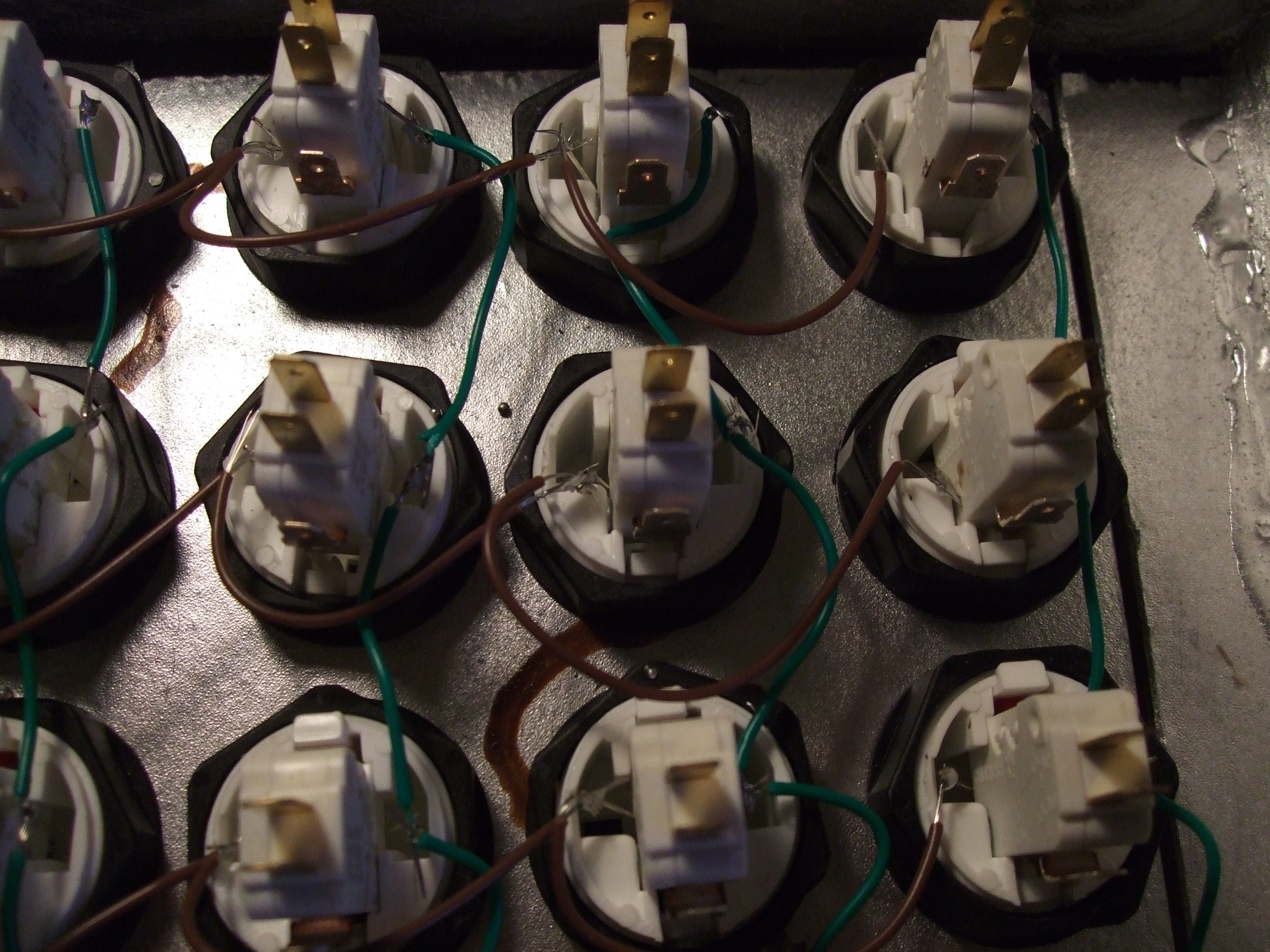
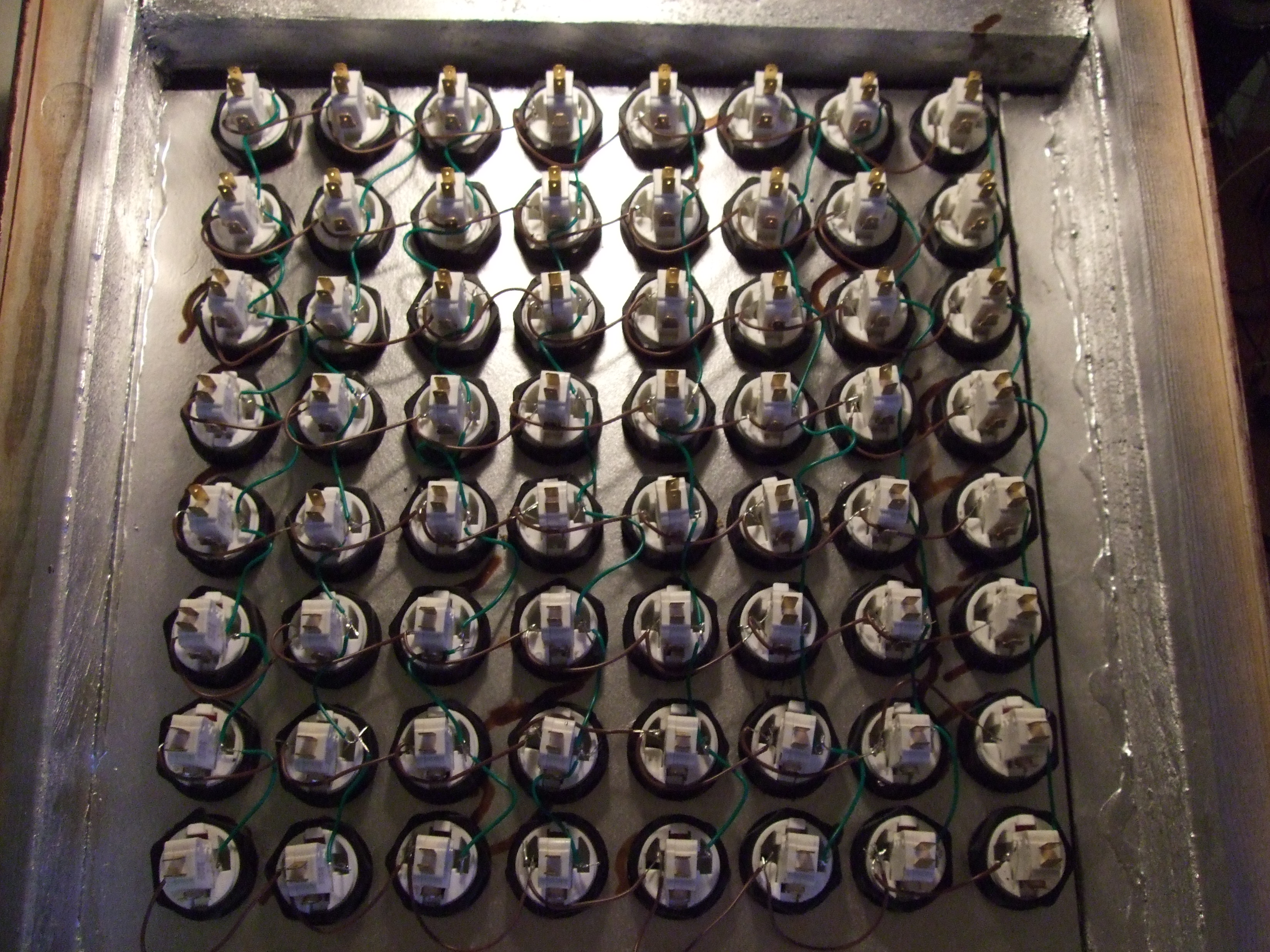
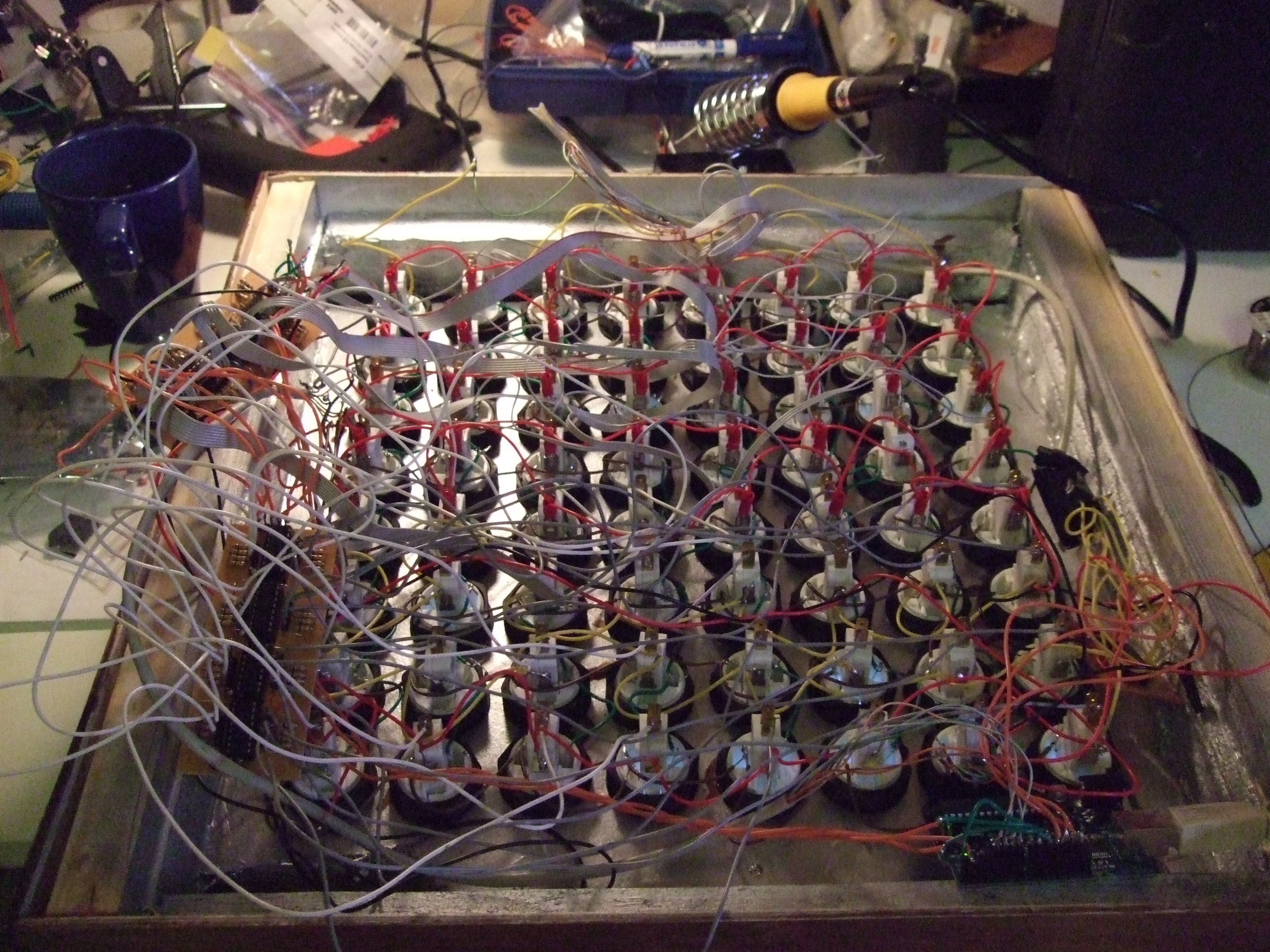
Connecting the LED’s in a matrix
First of all the buttons needed to be mounted in the box. To bad the paint had
made the wood swell just enough to not let the buttons slide through the holes.
Borrowed a round file and filed all the holes by hand (it did not work that well
with the sander in the picture). Then mounted the buttons

This was a very nice step, and it made me realize just how stylish the finished
product would be 🙂
And of-course you have to solder the together:
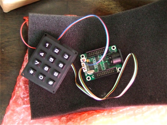
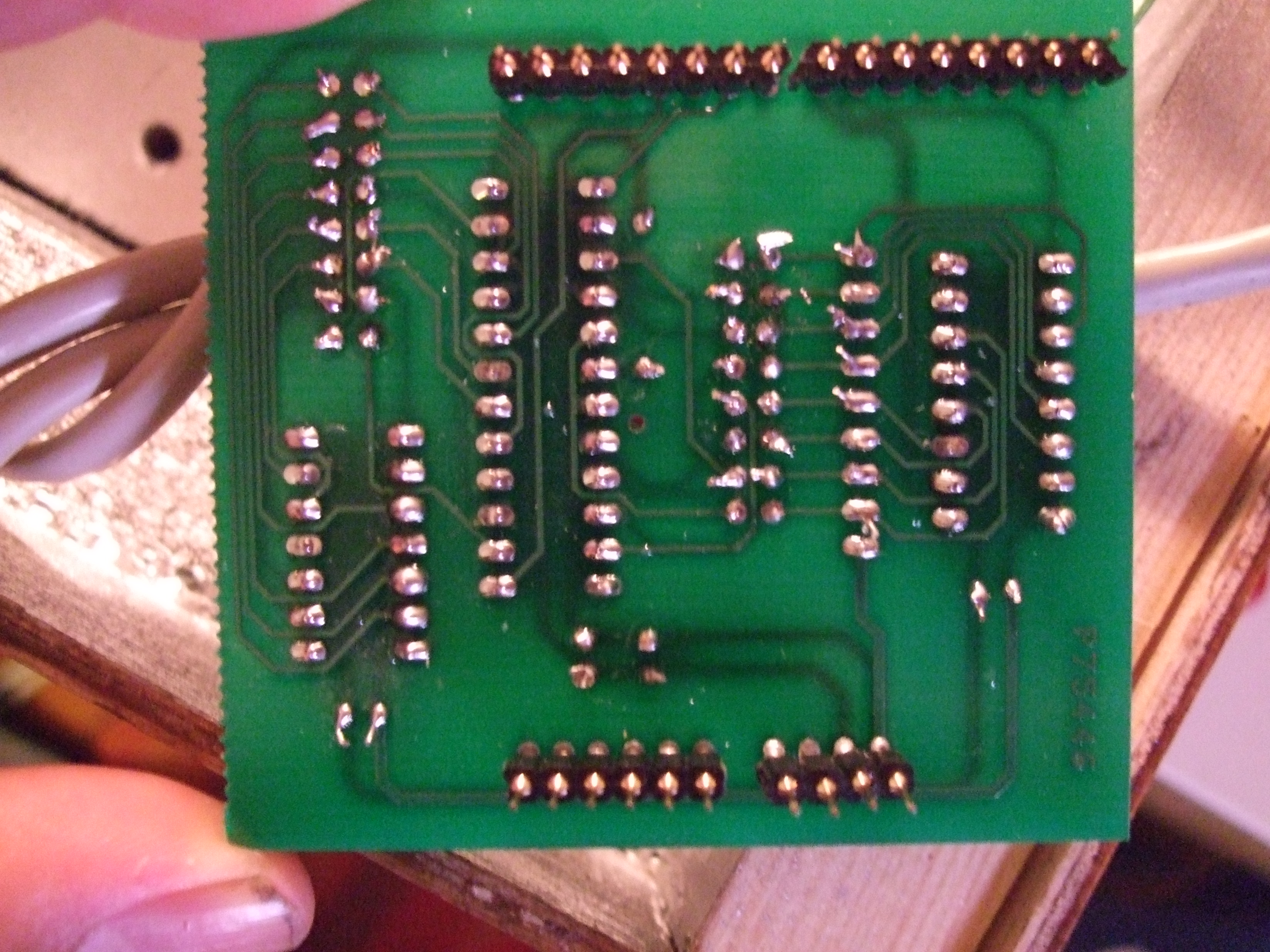
The Arduino-shield-failure.
I started this with the intention of using the Monome Arduino shield. No problem
there, bought it as part of a group-buy and when it arrived by mail I ordered the
parts. Soldering was easy-peasy and didn’t take long. Eager to test things I
hooked it up to the LED-matrix but I couldn’t get it to work. The Arduinome is made
to fit with Monome like plastic buttons and pcb from sparkfun. I didnt want to use
that, I was to much in love with my arcade buttons idea. Anyways my LED matrix did
not light up where it should although I tried with the Monome test max/msp patch and
loads of different MAX7219 Arduino examples from the Arduino site. I tried like a
gazillion different configurations and different source-code. I also bought not
one but two new LED Driver IC’s and tried breadboarding and loads of things.
Nothing worked, I spent most time of the project here. And I didn’t get it to work
at all. BIG FAIL. If this where a romantic comedy type of movie this is the
part where the guy looses the girl.
The shiftOut success.
If you look at the Arduino-site there is an example on how to get more out’s, i.e.
ShiftOut one. very nice, I got that working in like five minutes. a few minutes later
I had it all connected to my LED matrix and multiplexed via inputs on the Arduino.
Here is the program for it.
Led.pde
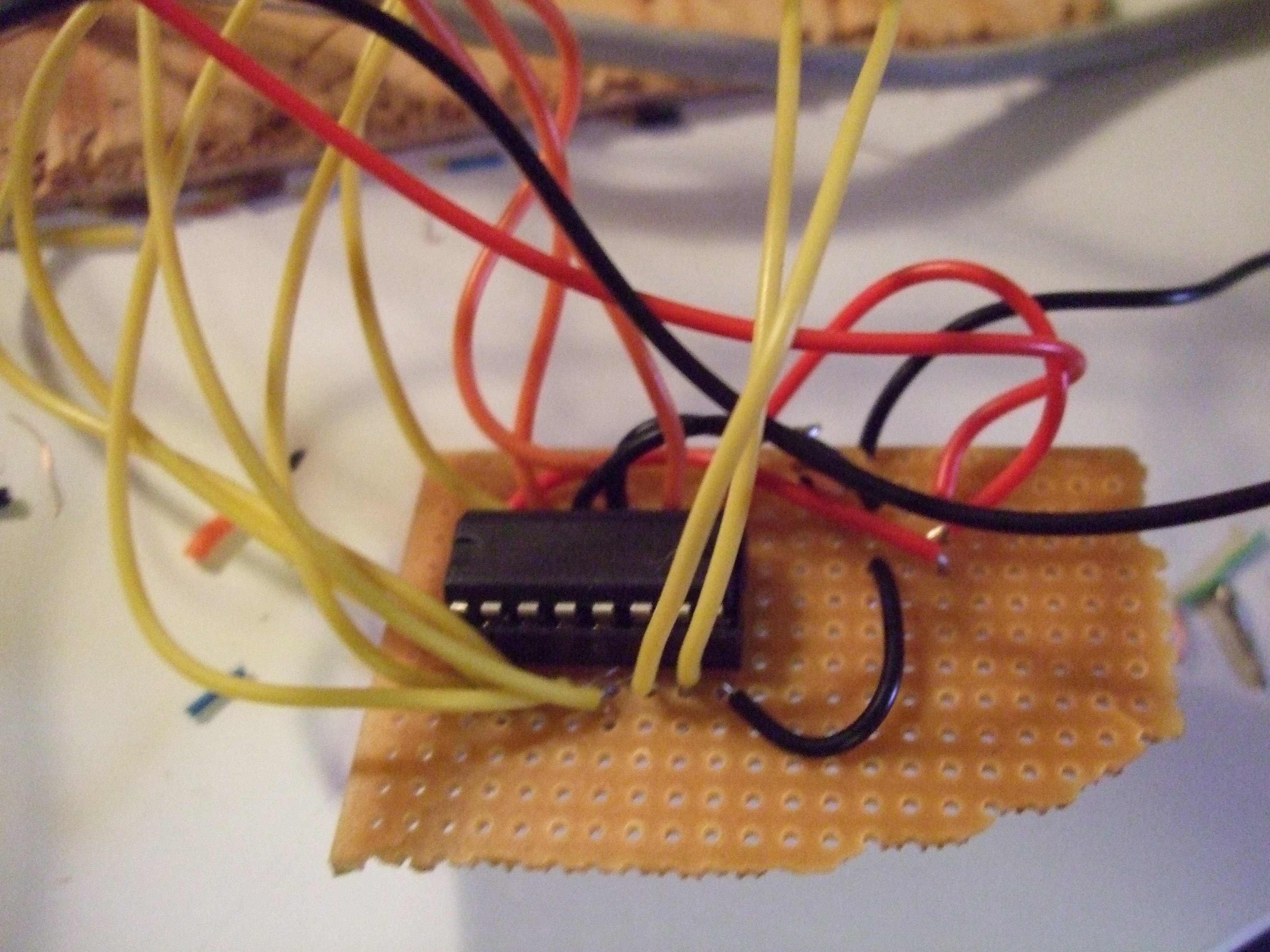
I’m very proud of this piece. I’s the first thing I’ve prototyped on a breadboard,
the moved to a protoboard and got it all working. Made me feel confident in myselve.
(this is where the strings come in and the boy get’s the girl back)
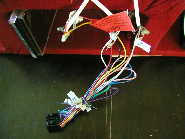
Replacing the shield altogether (aka the shiftIn success)
So now I’m thinking, what about removing that shield altogether? I suddenly remembered
me buying a few PCB’s a while back from www.ucapps.de specifically the DIN modules
(digital in) So I hooked up them to my buttons and viola, everything works Hooray!
actually it took a few hours soldering everything together and twice that looking for
shorts. but it works and I extended my previous LED test program so that it lights the
buttons that you press.
Led.pde
led_multiplex_3.zip
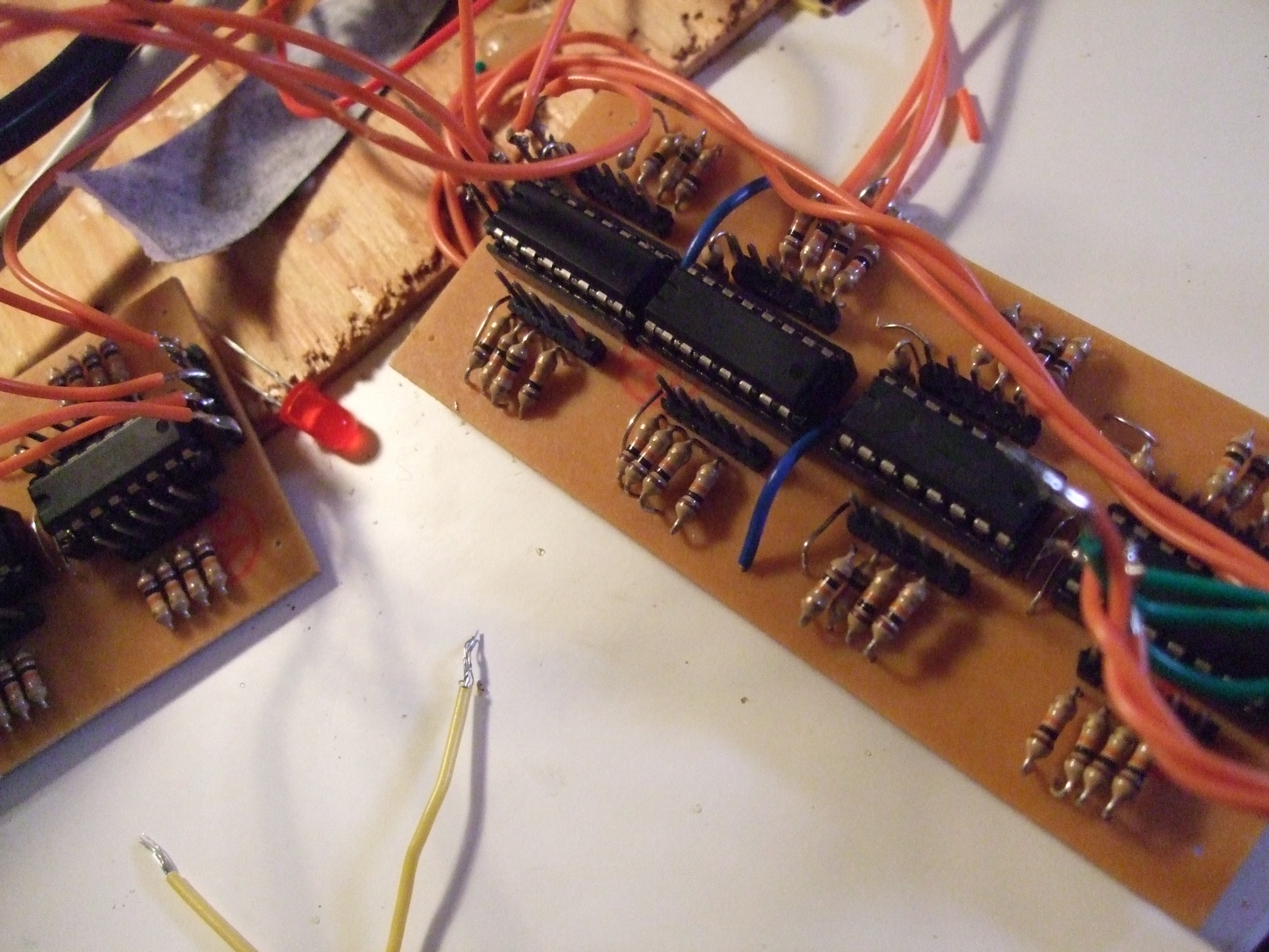
As you can se I really really wanted ppl to se parts of the back with all the work I
had with it.
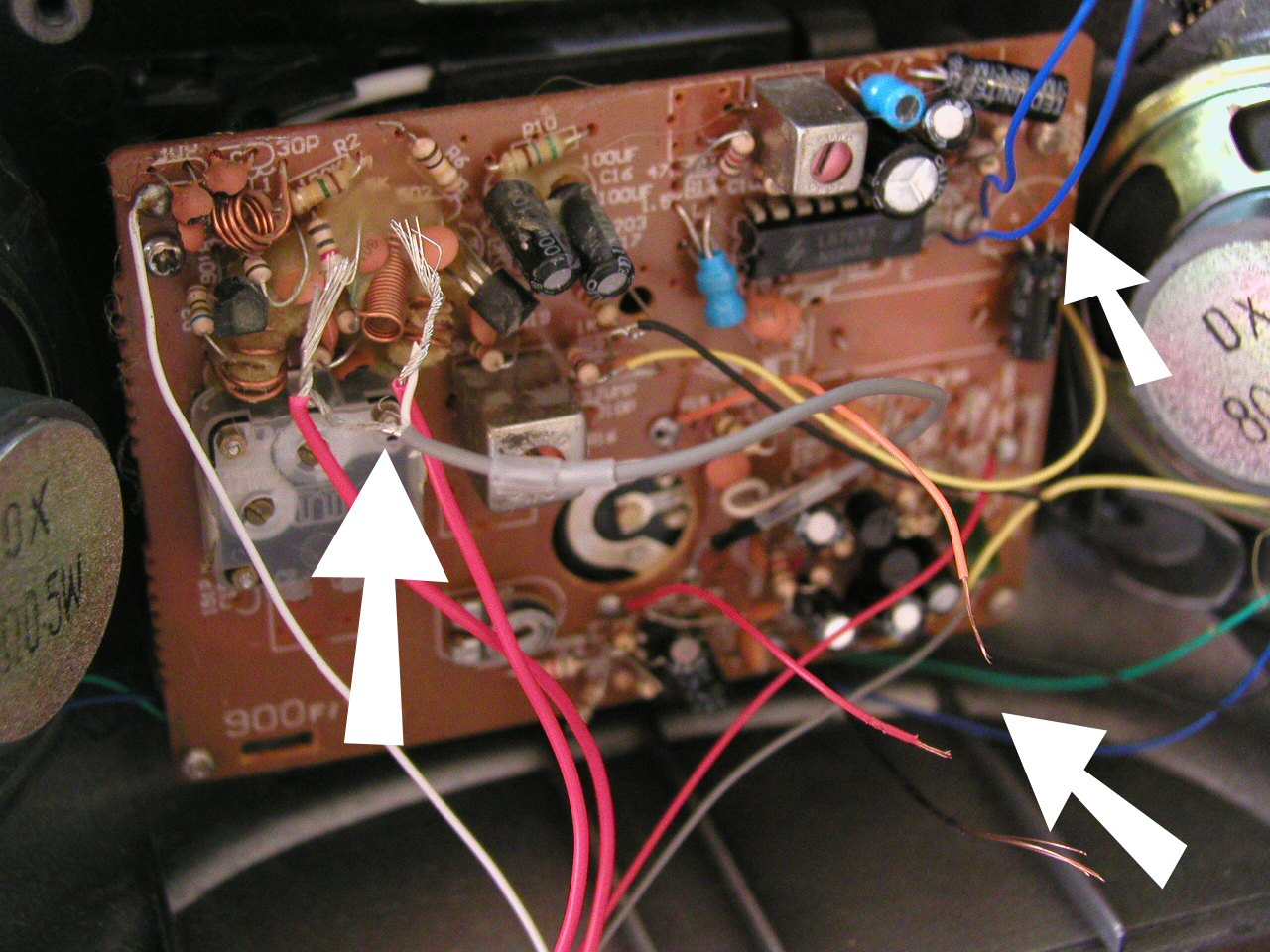
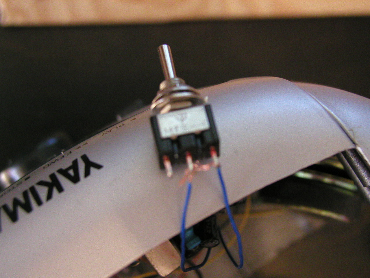
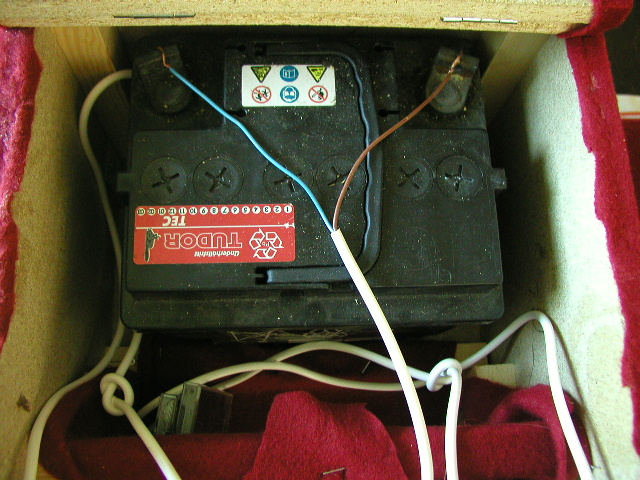
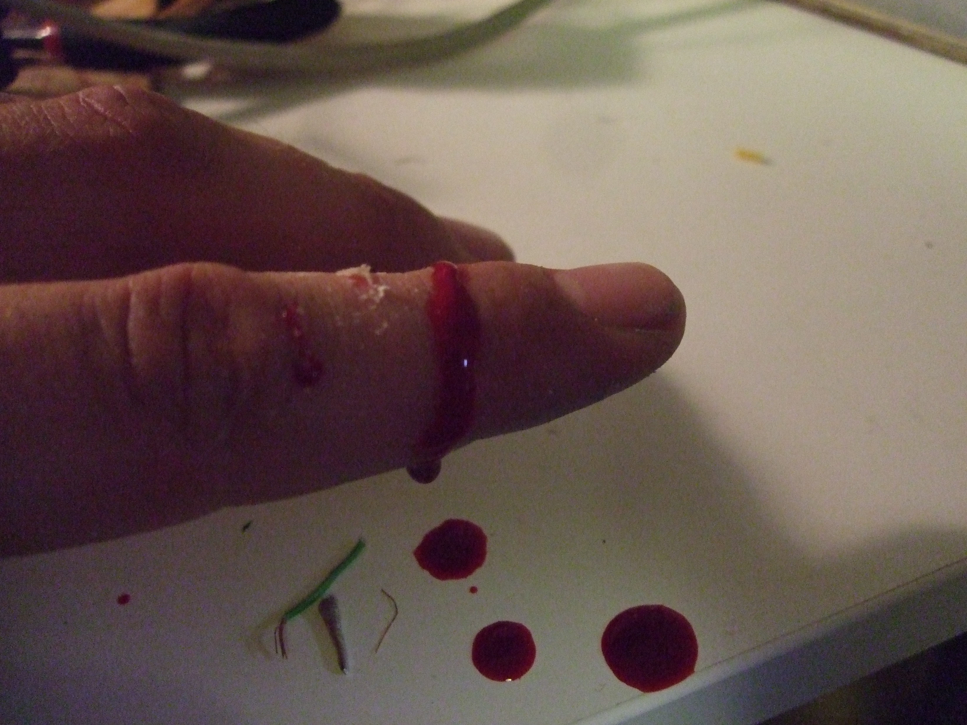
Adding midi-out to the soup.
Now that I had abandoned (saved for later) the shield I was thinking of diversing my
build. I really wasn’t satisfied with building the biggest Monome, the first with
LED’ed arcade buttons so I went for creating the first with a midi-out port. This was
an easy hack as it seems. To bad you need to use the UART that the USB uses to
communicate with the computer. And if you try using port 1 and 2 for multiplexing the
LED’s, strange lightning phenomena’s occur. I still will use the midi-out for for
something though. Since it was the only part of the build that hurt me so bad I
started bleeding.
Modifying the Arduinome source-code to utilize my hardware.
This could be a long chapter, but it won’t be. I started porting the Arduino-Monome
firmware to my hardware setup. Then the new Arduino firmware came out. So I used to
do that the conversion instead. But after optimizing the Arduinome-code (500 bytes
just by changing int blah 47; to #define blah 47) and dividing the source into
logical parts instead of the “singe big file” previously present. Anyways, I stopped
converting because of a number of reasons. 1. I got very little response. 2. I didn’t
get it it to work as I wanted. 3. I don’t really care about max/msp. So I stopped the
conversion and started creating my own setup. anyway: here is a zip with how far I got
in case you’re at all interested.
First signs of success, and a new name.
So I made an os x program that communicates via the serial-port to the Arduino. and that
program communicates back to the Arduino and creates a virtual midi-port. This is very
nice. I can with this setup create whatever programs I want without using max/msp. The
downside is that I cant use the already made max/msp, chuck and or whatever programs and
contraptions other people have created.
Anyways here is the source-code for the os x program (ccmidi class borrowed from
Monome-serial)
And the current firmware for the Arduino (a little borrowed here from the Monome firmware
(button de-bounce): both WIP and both will change and be added to. I’ll probably forget
to update this page so feel free to email me and ask for the newest version 🙂
there are 3 modes, first of is a press and it will play midi, second is a toggle and play,
and the third is a xoxo step sequencer that is far from finished. It will probably be
rewritten altogether. Perhaps before I publish this little text for the rest of the world 🙂
MOVIE:
Links:
http://docs.monome.org/doku.php?id=tech:ports:arduino
http://post.monome.org/comments.php?DiscussionID=2092
http://bricktable.wordpress.com/30/
http://createdigitalmusic.com/2008/08/20/arduinome-an-arduino-based-monome-clone-behind-the-scenes/
http://post.monome.org/comments.php?DiscussionID=2186&page=1
http://en.wikipedia.org/wiki/Arduinome
http://sourceforge.net/projects/arduinome/
http://www.arduino.cc/en/Tutorial/ShiftIn
http://www.arduino.cc/en/Tutorial/ShiftOut
http://www.ucapps.de
Final thoughts.
First of, If you only want an Monome, go buy one from monome.org. If you want to learn a little
bit about electronics. Try and get a hold of the shield. (I still have one that I wont use)
For me though it was a big learning project, and as such has taught me a lot and taken loads of
time. I hope in writing that I in some way can encourage and discourage you, dear reader. But
I can think of way worse places to learn about music and electronics then Arduino and Monome
communities.